How to Create a Norton’s Equivalent Circuit?
This article is intended to illustrate the steps required for creating a Norton equivalent circuit. All the concepts mentioned here build on the prior knowledge of simplifying circuits.
According to Norton's theorem, any two-terminal circuit, made up of fixed value resistances, of voltage sources, and of current sources, can be replaced by a single current source in parallel with a single resistance which will produce the same effects at the terminals.
There are four basic steps involved in creating the Norton equivalent circuit.
Step 1:
Identify the portion of the network for which the Norton equivalent circuit is to be determined. Label the two terminals as points A and B and remove the portion of the circuit that is not being included in the simplification (i.e. the load).
Step 2:
Remove and short circuit any voltage sources in the network and remove any open circuit any current sources. Calculate the Norton equivalent resistance as it appears between the open terminals previously labeled as points A and B in Step 1.
Step 3:
Return the sources in the network to their original state and position. Next, short circuit terminals A and B and calculate the Norton equivalent current, In, at that point in the circuit.
Step 4:
Draw the equivalent circuit using the values calculated for the Norton equivalent resistance and current.
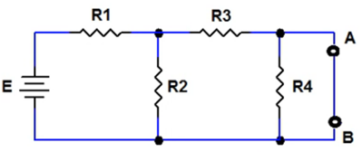
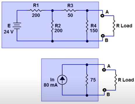
For example, we will use the simple resistive network shown in figure 1:
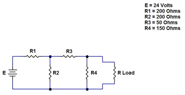
This network contains a single voltage source and four resistors. Values have been assigned to each component in the network. To determine the Norton equivalent circuit, follow the steps illustrated previously.
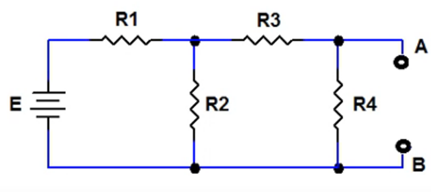
Step 1. Identify the portion of the network for which the Norton equivalent circuit is to be determined
1.1 Label the terminals connecting this portion to the remaining part of the circuit as points A and B.
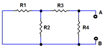
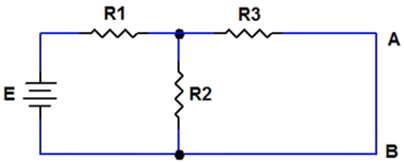
1.2 To complete the first step in the process, remove the portion of the network that is not being included in the simplification as shown in figure 2.
Step 2. Calculate the Norton Equivalent Resistance
2.1 Remove and short circuit the single voltage source that is present in the network as shown in figure 3.
2.2 Reduce this resistive network down to a single equivalent resistance.
To begin the reduction, calculate the equivalent resistance of R1 in parallel with R2 by using the product over sum rule as shown in figure 4a.
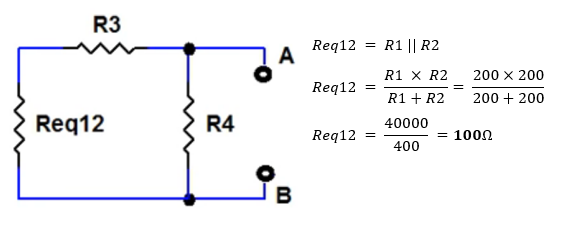
Next, sum the series resistance of R3 and Req12 to further simplify the circuit as shown in figure 4b.
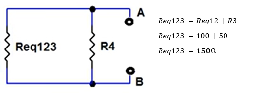
To complete the calculation of Rn combine the parallel resistances R4 and Req123.


The Norton equivalent resistance Rn for this sample network is equal to 75 ohms.
Step 3. Calculate the Norton Equivalent Current
3.1 Return all sources in the portion of the network for which the Norton equivalent circuit is being determined to their original state and position. Refer to Figure 2.
3.2 Create a short circuit between points A and B in the circuit with the circuit in this condition as shown in figure 5.
3.3 Calculate the Norton equivalent current In which flows through points A and B in the circuit.
It is important to note that there is a short circuit around resistor R4 which effectively removes it from the circuit. There will be no current flowing through this resistor in terms of calculating the Norton equivalent current resistor. R4 can be removed as it has no part in determining the current flowing between points A and B.
3.4 Calculate the remaining total resistance in the circuit and use Ohm's law to get the current flowing from the source with the circuit.


In the configuration of figure 6, R2 is in parallel with R3 and both of these are in series with R1. The total resistance is 240 ohms.
Next, use the value of E and the total remaining resistance to calculate the total current flowing from the source It.

Once the total current, It, flowing in the circuit is determined. Use the current divider rule to calculate the Norton equivalent current In.
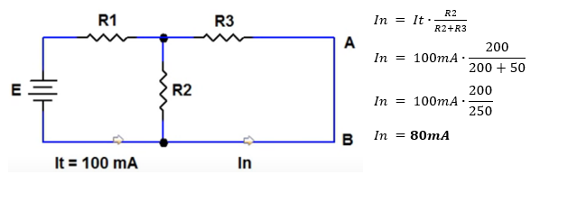
This current flows through R3 as well as through points A and B. The Norton equivalent current, In, for this sample network is equal to 80 mA.
Step 4. Draw the Equivalent Circuit
Use the calculated value for Norton current and Norton resistance to draw the equivalent circuit as shown in figure 8. The behavior of the original Network and the Norton equivalent circuit are identical with respect to points A and B.
This type of circuit reduction is extremely useful when attempting to determine the effects of varying load conditions on load voltage and current.
We hope that this has been helpful as a student or practicing Electronics technician. If you have any questions regarding the Electronics Technician program, feel free to get in touch with us at info@gbctechtraining.com or give us a call at 1-888-553-5333 to speak with a Program Consultant.